Frame Data – Work Points varying from Frame Data and FSD’s
(Revised: 04/01/08)
Clips & Holes are located slightly different
from Frame Data to FSD’s. The Building Editor is set up to be generic so you
can modify various Frame Members at the same time. FSD’s are showing exact
measurements for one Frame Member. Here are a few examples of how they differ.
|
|
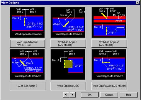
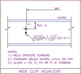
1.
In Frame Data, the Details shown are for locating various
Clips in the Web of a member. Every detail has a WP End 1 & a Dim A shown
locating the clips. Let’s look at the Web Clip Adjacent (WS-MC-04) Detail,
typical for a GC2. 2.
We will locate a GC2 for standard Inset Girts. The Dim A in
Frame Data measures from the Outside of the FO to the first hole. So to get
the Dim A, subtract 1 5/8” from 3 ½” (First hole from BL in my girt). This
means my Dim A in Frame Data will be 1 7/8” on any Frame Member requiring
this clip. |
|
|
3.
On FSD’s, the Dim A is measured from the Inside of the FO
to the first hole. This is an example of the Detail the shop will use to
locate the GC2 clip. |
|
FSD Dim A = 1 5/8” FO Thickness
+¼” Frame Data Dim A = 1 7/8” |
4.
It is important to remember when checking your FSD’s. The
dimension on the FSD’s is not what you will enter in Frame Data to fix a
location error. In Frame Data, you will add the Flange Thickness of that particular
Frame Member on to the corrected dimension from the FSD. |
|
5.
For more examples on FSD Work Points, refer to the Manufacturing
Reference Details. These details are called out on every detail that Building
Editor uses. Also, look closely at the details Frame Data uses when locating
items to help with the differences between the two. |
|